Sequence Diagrams Overview | Unified Modeling Language (UML)
Unified Modeling Language (UML) is a standardized modeling language in software engineering that provides a way to visualize the design of a system. Among the various diagram types UML supports, sequence diagrams are one of the most commonly used interaction diagrams.
Interaction Diagram
An interaction diagram captures how objects in a system interact. Visualizing these interactions can be complex, so different types of interaction diagrams are used to capture various aspects of interaction. A sequence diagram specifically illustrates the interaction between objects in a particular order, showing the sequence in which these interactions occur. These are also known as event diagrams or event scenarios. They are widely utilized by business professionals and software developers to document and understand requirements for new and existing systems.
Important Topics for Sequence Diagrams
Sequence Diagram Notation
-
Actors: In UML diagrams, an actor represents a role that interacts with the system and its objects. Actors are external to the system we are modeling and are depicted using stick figure notation. Multiple actors can be included in a sequence diagram.
-
Lifelines: A lifeline represents an individual participant in a sequence diagram and is displayed as a rectangle (head) with its name and type, located above a vertical dashed line (stem). Lifelines depict objects internal to the system, unlike actors which are external.
-
Messages: Communication between objects is depicted using messages that appear sequentially on the lifeline. Messages are represented using arrows and form the core of a sequence diagram. They can be classified into several types:
- Synchronous Messages: Wait for a reply before the interaction can proceed, represented by a solid arrowhead.
- Asynchronous Messages: Do not wait for a reply and are represented by a lined arrowhead.
- Create Messages: Used to instantiate a new object, depicted with a dotted arrow and the create label.
- Delete Messages: Used to delete an object, represented by an arrow terminating with an 'X'.
- Self Messages: Messages an object sends to itself, shown with a U-shaped arrow.
- Reply Messages: Indicate a message is sent back from the receiver to the sender, represented by a dotted line with an open arrowhead.
- Found Messages: Represent an unknown source sending a message, shown with an arrow pointing towards a lifeline from an endpoint.
- Lost Messages: Depict a scenario where the recipient is unknown, represented with an arrow from a lifeline to an endpoint.
Guards
Guards are conditions used to restrict the flow of messages until a certain condition is met. They are essential for informing software developers about the constraints within a system or process.
Example of Sequence Diagram
Consider a sequence diagram for an emotion-based music player. The user opens the application, and the sequence of interactions follows in order. This visual representation helps in understanding the flow and the interactions between different objects in the system.
Challenges of Using Sequence Diagrams
While sequence diagrams are beneficial for visualizing system interactions, they can become complex for large systems with numerous interactions. Ensuring accuracy and maintaining readability are common challenges.
This rephrased version maintains the original meaning and structure but uses different wording and sentence structures to convey the same information.
Advanced Sequence Diagram Concepts
Combined Fragments
Combined fragments are used to represent conditional logic in sequence diagrams. They are essential for modeling complex interactions and can be classified into several types:
- Alternative (alt): Represents a choice between different paths. Only one path is executed based on a condition.
- Option (opt): Depicts an optional interaction that occurs only if a specified condition is true.
- Loop: Indicates that a sequence of interactions is repeated. The loop can be controlled by a guard condition.
- Break: Represents a scenario where a sequence is interrupted, and control is transferred outside the current sequence.
- Parallel (par): Denotes interactions that occur concurrently.
- Critical Region (region): Highlights interactions that must be executed in a mutually exclusive manner.
- Negative (neg): Used to illustrate invalid interactions.
Interaction Use
Interaction use allows the inclusion of references to other sequence diagrams within a sequence diagram. This is useful for reusing common interaction sequences and maintaining a modular design.
State Invariants
State invariants are conditions that must hold true at a specific point in a lifeline. They are used to ensure that the system adheres to certain constraints during the interaction.
Practical Applications of Sequence Diagrams
Business Process Modeling
In business process modeling, sequence diagrams help in visualizing the flow of activities and interactions between different business entities. They provide a clear representation of how business processes are executed over time.
System Design and Architecture
Sequence diagrams are invaluable in system design and architecture. They help architects and developers understand the flow of control and data between different system components, ensuring that the system design meets the desired requirements.
Debugging and Testing
During the debugging and testing phases, sequence diagrams can be used to trace the flow of interactions and identify potential issues. They provide a visual aid for understanding how different parts of the system interact, making it easier to pinpoint bugs and errors.
Conclusion
Sequence diagrams are a powerful tool in the UML arsenal, providing a detailed view of the interactions between objects in a system. Understanding the various components and advanced concepts of sequence diagrams is crucial for effectively modeling complex systems. By leveraging sequence diagrams, professionals can ensure that their system designs are robust, efficient, and meet the specified requirements.
This concludes our detailed overview of sequence diagrams in UML. If you have any further questions or need more specific information, feel free to ask!
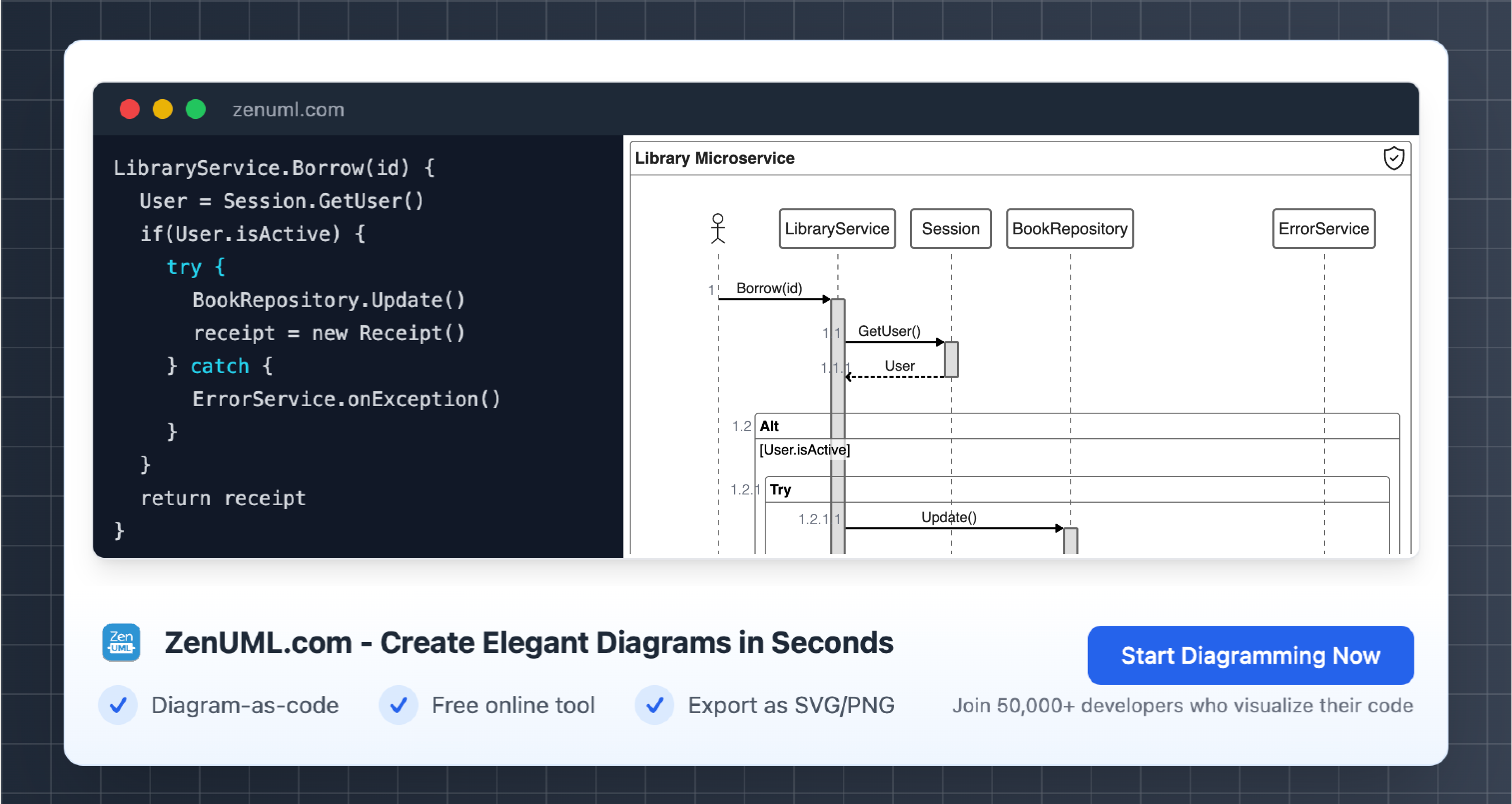
Try ZenUML now!
Find out comprehensive guide here.