
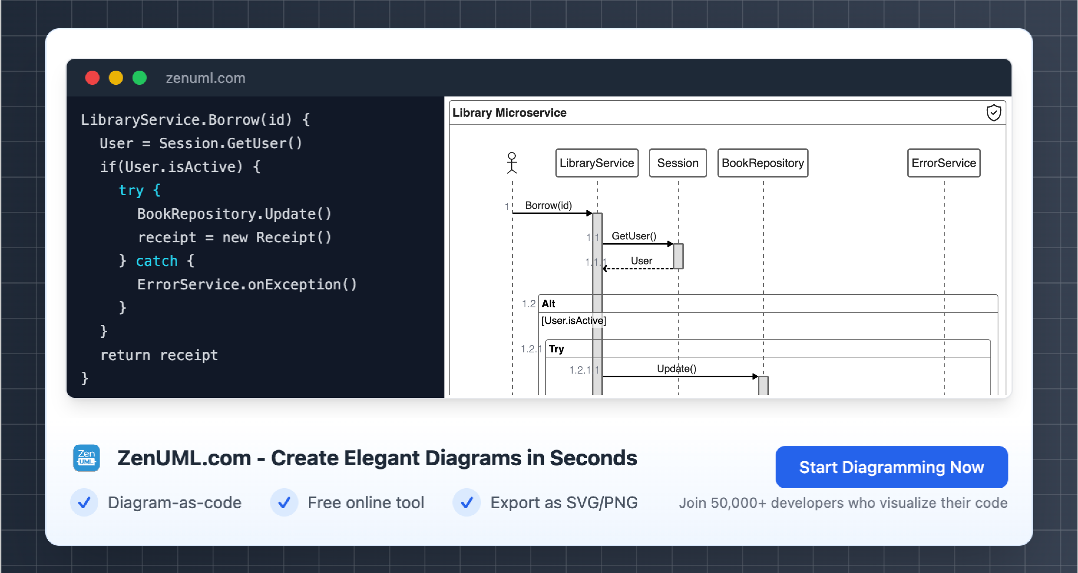
Try ZenUML now!
Introduction
Unified Modeling Language (UML) is a standardized modeling language used in software engineering and systems design. It provides a common vocabulary and notation set that allows developers, designers, and business analysts to visualize, specify, construct, and document a software system.
Within the UML suite of diagrams, sequence diagrams are particularly useful for modeling object interactions over time. They capture the order in which messages are passed between objects in a system. This chronological perspective makes sequence diagrams great for visualizing logic, especially complex workflows and processes that involve several objects.
In this article, we will cover the basic concepts and definitions around UML sequence diagrams. We will explore what sequence diagrams are, what they are used for, and their key components. Our goal is to provide a high-level overview of sequence diagrams for those new to UML. We will not go in-depth into how to actually create sequence diagrams or use specialized sequence diagram software. By the end, readers should understand the purpose and utility of sequence diagrams in the software design process.
What is a Sequence Diagram in UML?
A sequence diagram is a type of interaction diagram in the Unified Modeling Language (UML) used to model the flow of logic within a system in a visual manner. Sequence diagrams specifically depict the chronological order of interactions between various objects in a system.

Unlike a collaboration diagram, which shows all the interactions for a specific object, a sequence diagram shows just one sequence of interactions. So sequence diagrams are a way to visualize the order in which operations happen between objects within a use case. This provides a high-level overview of system behavior and the logical flow of a process.
Sequence diagrams are especially useful in fields like software development and systems engineering for documenting requirements, communicating design, testing scenarios, and generally visualizing the dynamic behavior of a system. They allow developers, designers, and business analysts to see complex processes from a higher level before implementation.
Some key advantages of using sequence diagrams are that they are easy to understand for both technical and non-technical stakeholders, they enable early validation of designs, and they facilitate communication between different teams involved in a project. Overall, sequence diagrams are an essential UML modeling technique for understanding system behavior in visual form early in the development lifecycle.
The Significance of Sequence Diagrams in Industry
Sequence diagrams play a vital role in the design and development of software systems and other complex processes. By visually depicting the flow of logic and events between components, sequence diagrams enable stakeholders to understand the overall architecture and interactions within a system. This makes them invaluable tools for communication and validation during the software development lifecycle.
For systems analysts and software architects, sequence diagrams provide a way to conceptualize and model system behavior early in the design process. The diagrams help analysts think through logic, identify components and relationships, and validate proposed system workflows. Architects use sequence diagrams to communicate designs to developers and get stakeholder sign-off.
For developers, sequence diagrams document the essential logic and component interactions needed to implement system functions. They serve as a helpful visual aid for understanding program logic and structure. Developers can reference sequence diagrams when writing code to ensure they are implementing interactions and events properly.
For testers, sequence diagrams offer an abstract overview of system behavior to inform test planning and test case development. By outlining key flows and logic, testers can systematically test system components and their relationships. Sequence diagrams enable complete validation of system functionality.
For stakeholders and end users, sequence diagrams provide a high-level view of system processes, interactions, and events. Though abstract, the diagrams build understanding of how a system is intended to work. Stakeholders can review sequence diagrams to validate workflows before system implementation.
By clearly communicating logic, events, and processes, sequence diagrams bring alignment for all stakeholders involved in system and software development. Their widespread use demonstrates their value in designing, building, and testing robust systems.
Basic Concepts of Sequence Diagrams
Sequence diagrams are incredibly useful visual modeling tools that help software developers understand and communicate the flow of logic within a system. At their core, sequence diagrams illustrate how different components in a system interact with each other and in what order those interactions occur.
The key to sequence diagrams is their ability to capture the dimension of time and sequence. By visually mapping out the chronological flow of messages passed between components, sequence diagrams make it easy to see the sequential logic and overall process flow. Developers can use them to model everything from simple function calls to complex distributed systems.
Unlike class diagrams or entity relationship diagrams, sequence diagrams are interaction-centric and behavior-focused. They dive into the details of system operation, depicting the messages and participating objects needed to perform a specific function or task. This level of specificity is incredibly valuable for grasping complex flows and identifying potential failure points or performance bottlenecks.
Overall, sequence diagrams are an intuitive but powerful communication tool for development teams. They promote better understanding of system behaviors and interactions so that software can be designed, built, and maintained more efficiently. Whether used for documentation, upfront design, or even runtime tracing, sequence diagrams are an indispensable part of modeling software systems.
Sequence Diagrams: Usage in Various Industries
Sequence diagrams are an invaluable tool utilized across countless industries to map out complex workflows and interactions between components in a system. By visually representing the flow of logic and events over time, sequence diagrams promote clearer communication and documentation. Here are some examples of how different sectors leverage the power of sequence diagrams:
In software development, sequence diagrams are ubiquitous in modeling the flow of function calls and object interactions needed to implement specific features. They allow developers to flesh out high-level designs and ensure all parties are on the same page before diving into code. The diagrams enhance modularity and testability by encouraging well-defined interfaces between components.
In hardware design and embedded systems, sequence diagrams help designers coordinate the precise timing between electronic components and logic gates. Simulating the exact sequencing of signals is crucial for achieving proper functioning of the overall system. Diagrams make this timing intuitive during the design phase.
For business analysts and systems architects, sequence diagrams aid in strategizing organizational processes from end-to-end. Mapping the handoffs between human tasks, computer systems, and external touchpoints highlights optimization opportunities. They also pinpoint risks around bottlenecks, single points of failure, and poor integration.
In complex undertakings involving many moving parts, sequence diagrams enable leaders to effectively communicate visions and rally teams around a common understanding. The diagrams clearly illustrate how each contributor fits into the big picture workflow. This improves coordination and ensures all dependencies are met for project success.
Conclusion
In summary, a sequence diagram is a crucial component of the Unified Modeling Language that allows developers to visualize the sequence of interactions between objects in a system. By mapping out the order of method calls between objects, sequence diagrams provide an abstract overview of key processes and workflow in an application.
While we only scratched the surface in this introductory post, sequence diagrams enable developers to both document and validate their understanding of complex software systems and architectures. By breaking down processes into discrete steps and objects, sequence diagrams promote better communication between team members and stakeholders.
Mastering the ability to create accurate and meaningful sequence diagrams is a highly useful skill for any software professional. With some practice and reference to UML documentation, anyone can start benefiting from leveraging sequence diagrams in their development process.
There is still much more to explore when it comes to UML and the family of diagrams it provides. Use case diagrams, class diagrams, state machine diagrams and others each offer their own value. Integrating multiple UML diagram types can enable even deeper system comprehension and modeling.
Hopefully this post provided a solid foundation for understanding the purpose and utility of sequence diagrams. Feel free to build on this knowledge by expanding into other areas of UML - the universal language of software engineering has many insights to uncover.
Zenuml detailed feature roadmap available here.