
Introduction
In the world of software development, understanding and effectively implementing control flow structures is a crucial skill. One such fundamental control flow structure is the if-else logic, which allows programmers to make decisions based on specific conditions. To better visualize and comprehend the execution of this logic, sequence diagrams can be a powerful tool.
Sequence diagrams, a part of the Unified Modeling Language (UML), are a graphical representation of the dynamic behavior of a system. They depict the interaction between different entities, known as "actors," and the messages exchanged between them over time. By leveraging sequence diagrams, developers can gain a deeper understanding of the flow of control and decision-making processes within their applications.
In this blog post, we will explore the intricacies of if-else logic and how to effectively represent it using sequence diagrams. We will delve into practical examples, provide step-by-step guidance, and showcase the benefits of this approach.
Understanding If-Else Logic
The if-else logic is a fundamental control flow structure in programming that allows for decision-making based on a specified condition. The general structure is as follows:
if (condition) {
    // Code to be executed if the condition is true
} else {
    // Code to be executed if the condition is false
}
In this structure, the if statement evaluates a condition, and if it is true, the code block within the if statement is executed. If the condition is false, the code block within the else statement is executed instead.
This decision-making process is essential in programming, as it enables applications to adapt their behavior based on various scenarios, user inputs, or system states. Mastering the if-else logic is a crucial step in becoming a proficient programmer.
Representing If-Else Logic with Sequence Diagrams
Sequence diagrams offer a visual representation of the interactions between different entities or objects within a system over time. By incorporating if-else logic into sequence diagrams, developers can effectively communicate the decision-making processes and the resulting flow of control.
To represent if-else logic in a sequence diagram, we can use the following elements:
- Actors: The entities or objects involved in the interaction, such as users, systems, or components.
- Messages: The communication between the actors, represented by arrows between the actors.
- Conditional Operators: The if-else logic, represented by decision points or branching in the sequence diagram.
Here's an example of how to represent if-else logic in a sequence diagram using the ZenUML diagramming language:
@User "User"
@System "System"

// System evaluates condition with sync message
"User" -> "System"."EvaluateCondition"() {
  // Depending on the condition, System responds to User
if("Condition is True"){
  @return "System" -> "User": ResponseA
}
else {
  @return "System" -> "User": ResponseB
}
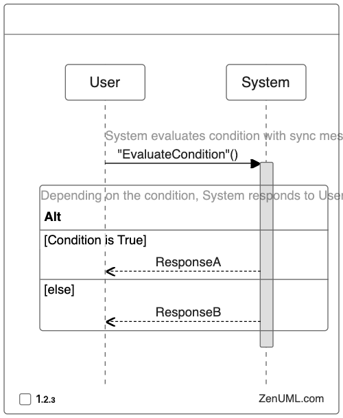
In this example, the user sends a request to the system, and the system evaluates a condition. Depending on the result of the condition, the system sends either Response A or Response B to the user.
The if and else keywords in the ZenUML syntax represent the if-else logic, with the condition being evaluated in the if block and the alternative action being executed in the else block.
By using sequence diagrams, developers can visually depict the flow of control, the decision-making process, and the interactions between different entities within their application. This approach can enhance understanding, facilitate communication, and aid in the design and implementation of complex software systems.
Practical Examples of If-Else Logic in Sequence Diagrams
To further illustrate the application of if-else logic in sequence diagrams, let's explore a few practical examples.
Example 1: User Authentication
In this example, we'll represent the user authentication process using if-else logic in a sequence diagram.
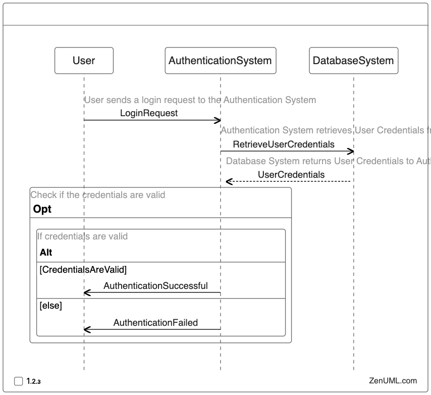
In this sequence diagram, the user initiates a login request to the authentication system. The authentication system then retrieves the user's credentials from the database system. Based on the validation of the credentials, the authentication system either sends an "Authentication Successful" message or an "Authentication Failed" message to the user.
Example 2: Online Shopping Cart
Let's consider an online shopping cart scenario, where the if-else logic is used to handle different checkout scenarios.
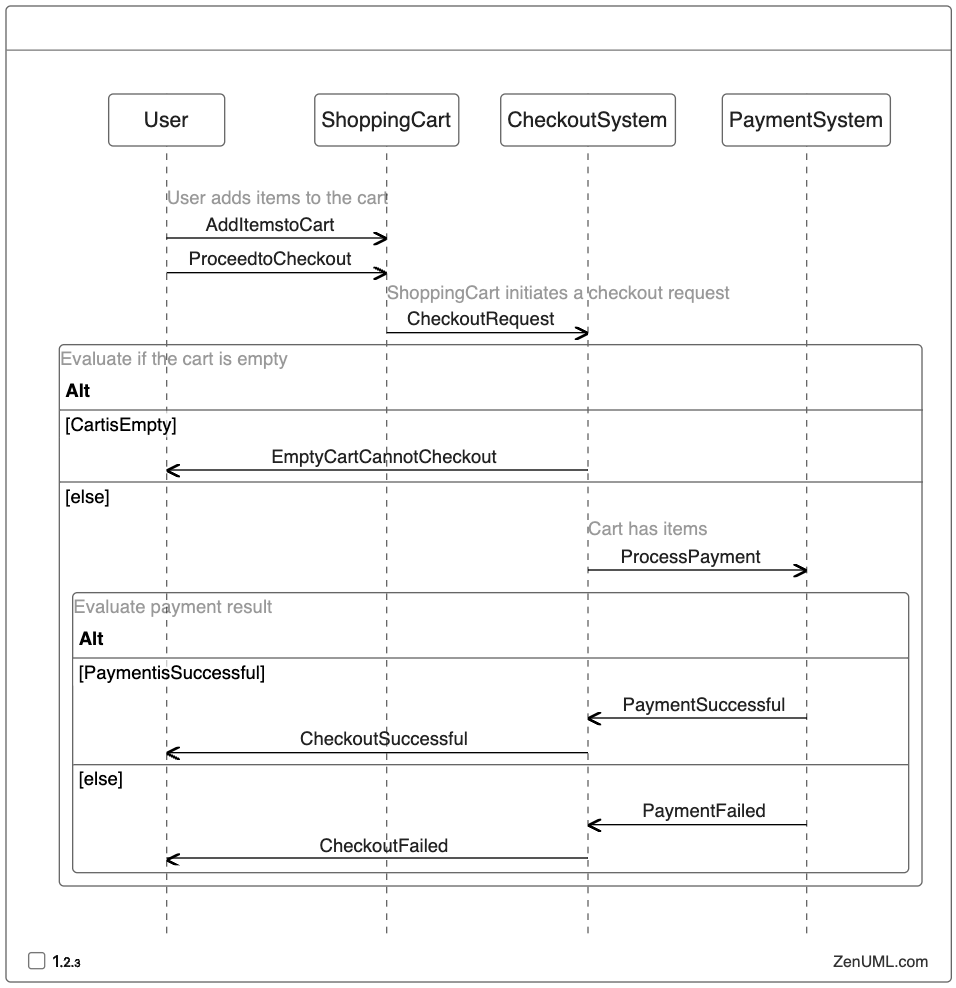
In this sequence diagram, the user adds items to the shopping cart and proceeds to the checkout. The checkout system first checks if the cart is empty, and if so, it notifies the user that they cannot proceed with the checkout. If the cart has items, the checkout system initiates the payment process with the payment system. Depending on the success or failure of the payment, the checkout system sends the appropriate response to the user.
Example 3: Notification System
In this example, we'll represent a notification system that sends different types of notifications based on user preferences.
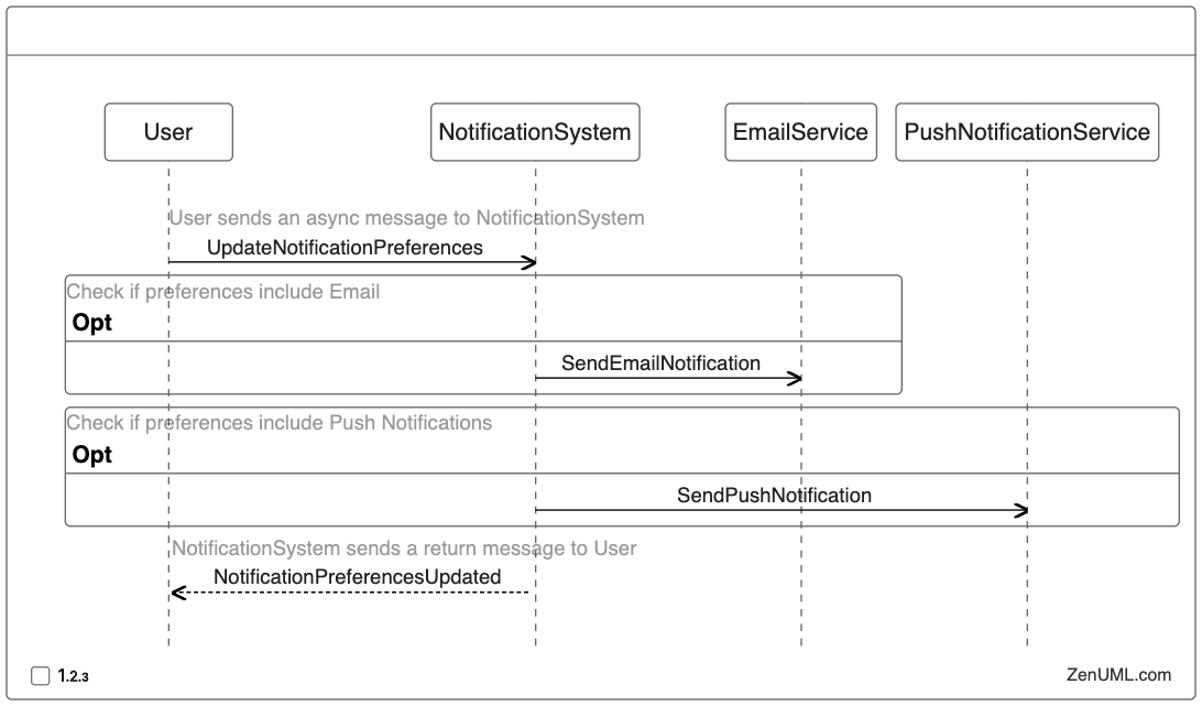
In this sequence diagram, the user updates their notification preferences with the notification system. The notification system then checks the user's preferences and sends the appropriate notifications using the email service or push notification service, or both, depending on the user's preferences. Finally, the notification system confirms the update to the user.
These practical examples demonstrate how if-else logic can be effectively represented and communicated using sequence diagrams. By visualizing the decision-making process and the resulting flow of control, developers can better understand, design, and communicate the behavior of their applications.
Benefits of Using Sequence Diagrams for If-Else Logic
Incorporating if-else logic into sequence diagrams offers several benefits for software development:
-
Improved Communication: Sequence diagrams provide a visual representation of the decision-making process, making it easier for developers, stakeholders, and team members to understand and discuss the application's behavior.
-
Enhanced Understanding: By depicting the flow of control and the interactions between different entities, sequence diagrams help developers and team members better comprehend the implementation of if-else logic within the system.
-
Easier Debugging: Sequence diagrams can serve as a valuable tool for debugging and troubleshooting. By tracing the flow of control and identifying the decision points, developers can more easily pinpoint and resolve issues related to if-else logic.
-
Facilitate Design and Planning: When planning and designing software systems, sequence diagrams can help developers identify and address potential edge cases, ensure the proper handling of conditional logic, and optimize the overall system architecture.
-
Improved Documentation: Sequence diagrams can be included in project documentation, providing a clear and concise representation of the if-else logic within the application. This can significantly enhance the maintainability and understanding of the codebase for future developers.
-
Standardized Representation: By following the UML standard for sequence diagrams, developers can leverage a common, widely recognized notation to represent if-else logic, facilitating collaboration and knowledge transfer within the software development community.
Conclusion
In the world of software development, if-else logic is a fundamental control flow structure that plays a crucial role in decision-making and application behavior. By leveraging sequence diagrams, developers can effectively represent and communicate the execution of if-else logic, enhancing overall understanding, design, and implementation of software systems.
Try ZenUML now!
Zenuml detailed feature roadmap available here.